Phase 1. Design
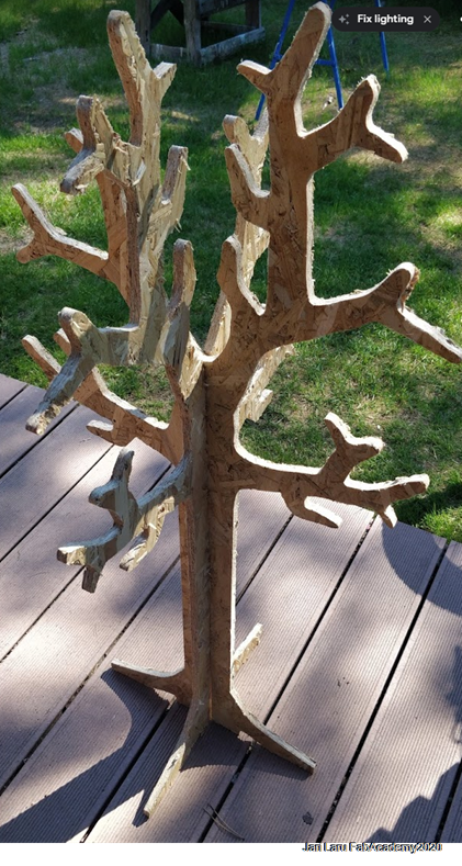
In this week our task was to design something big. I had vision about the tree which would be cable organizer and holder for VR glasses in my classroom (KTK149).
Some examples from the past Fabacademy years
I got many ideas for my own implementation from the examples mentioned above. For example, I followed idea by Chunwei GE to make replica of Connox Tree Coat Stand in my design. Furthermore, I got ideas of joint from all of previous works and idea for stand from Peetu's work.
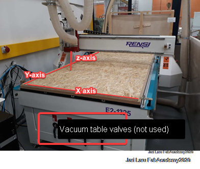
In this year we had to design "something big" by using OSB (Oriented Standard Board) as a material (thickness was 11mm)
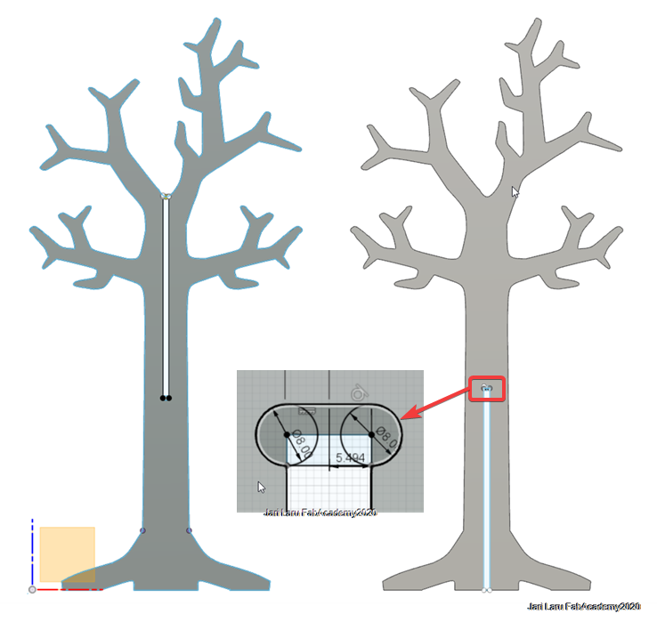
My design steps for tree-shaped coat rack
I started from the same phase than Chunwei Ge. I used "Swedese - Tree Coat Stand" as a source of inspiration. However, because this stand was under "all rights reserved" copyright, I modified it a lot to create original artefact, which is as much as possible unique product. For example, I added and modified branches of the tree and designed different stand for it
Generally, my path to manufactured tree coat stand wasn't straight although I considered that this kind of design would be quite easy to design and manufacture. In this documentation you will see that I ended up into problems when creating tool paths, but finally learnt what was to reason for the difficulties
Starting point: Transforming bitmap photo into Fusion 360 sketch
converting bitmap image to vector format
Editing original image in Gimp
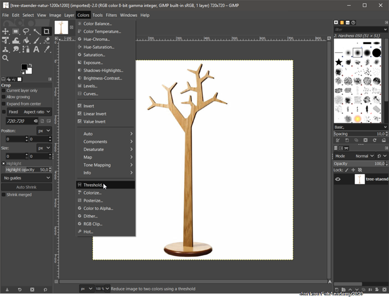
First photo of tree coat stand was turned into black white version by using treshold tool (Colors > Threshold)
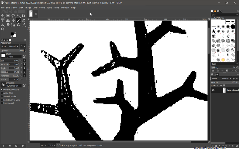
Then some parts of the tree rack were fixed by using paintbrush (see the photo). After that image was exported by using ctrl+e shortcut.
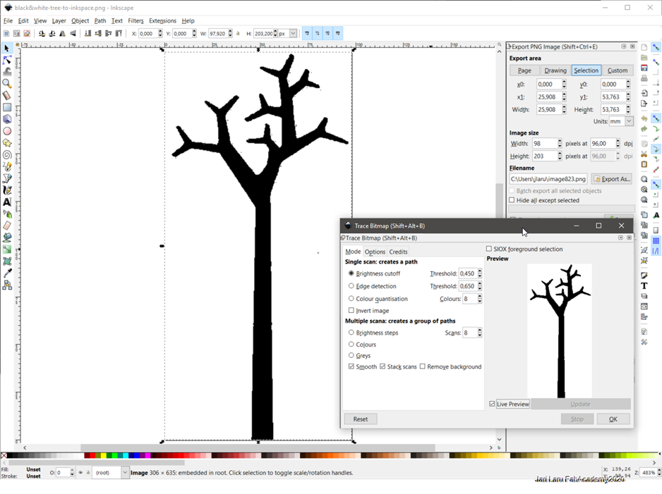
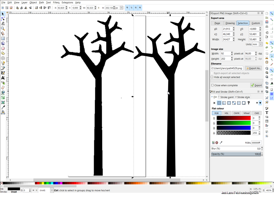
Next I opened bitmap image into Inskcape and used trace bitmap -tool (shortcut shift + alt + b) to create vector version of the three rack.
Tool did create new (vector) version of the three and after that bitmap version was deleted and vector version was saved to be used later on in the Fusion 360
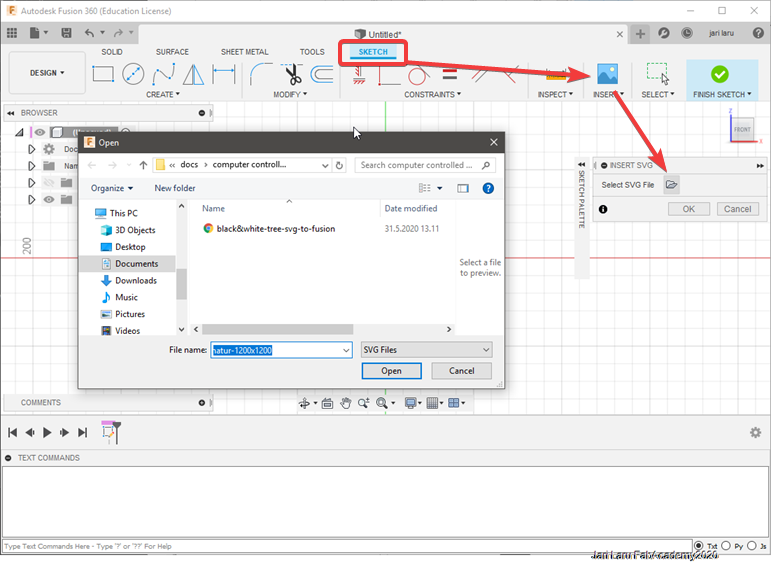
Inserting SVG file into sketch
Adding SVG file into Fusion360 is easy task:
- Activate sketch mode
- Choose Insert (and SVG)
- In the pop-up menu, click select SVG file and choose correct file
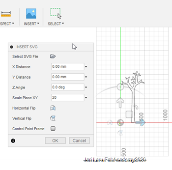
Settings for inserting SVG
Next it was possible to change orientation of the sketch of tree (it wasn't anymore svg) and scale it. I did scale it to 20x compared to import result
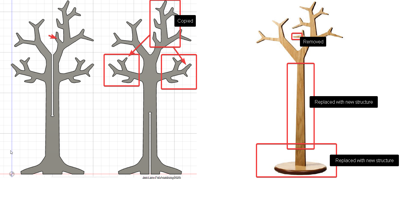
Sketch was modified by removing and copying parts of the tree
I had to make some changes to original designs:
A. Small part of top branch was deleted: it would block joint between parts.
B. Top branch was copied and attached to the new trunk of the tree
C. Trunk of tree was deleted and re-designed to accommodate slots (see phase E.) inside of it
D. Platform of tree was also deleted and re-designed for same reason
E. In addition to that slots were designed so that two separate trees can stand up in a 90 degree angle.
A. Modifying a part of top branch to remove potential obstacle for joined trees
In this phase I did modify top branch by deleting a part and fixing the rest, because it would be obstacle for joints
- Part of branch was deleted by using "trim" and "break" tools (Both can be found from "modify" -menu)
- Rest of the branch was fixed by drawing splines (curvy lines) with "fit point spline" tool (can be found from "create menu")
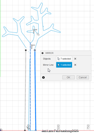
B. Top branch was copied, duplicated and attached to the new trunk of the tree
In this phase I did copy top branch to the left side of the trunk and then it was mirrored by using construction line in the middle of the tree as mirror line
-
Top branch was separated of rest of the sketch by by using trim and break -tools (modify menu)
- Then branch was copied and moved to new place. Orientation was changed 90 degrees. (select a part of the sketch and then click right mouse button)
- Next I used mirror tool to copy branch to the right side of the trunk
- To finalize this design, both branches were connected to trunk by using fit point spline (create menu) and extend (modify menu) tools
C. Designing new trunk to the tree
In this phase I did create new trunk for the tree.
-
I started this it by drawing right side of the trunk by using line -tool (by pressing L)
- Then I draw another vertical line to the middle of the tree. I switched it into construction line (right click and change between line / construction line )
- Next I used mirror tool to copy line to left side
- I finalized connections to the branches by using fit point spline-tool
D. Designing new platform to the tree
In this phase I did design platform to tree.
-
I started this it by drawing left side of the platform by using line and fit point spline -tool (I used those tools also in my earlier phases)
- Then I draw another vertical line to the middle of the tree. I switched it into construction line (right click and change between line / construction line )
- Next I used mirror tool to copy left side of the platform to right side of the mirror line
- I finalized connections to the rest of the sketch by using fit point spline-tool
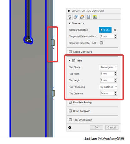
E. Designing slots to tree trunks
Last thing was to design slots to both tree trunks. The rack is designed so that two pieces will stand up in 90 degree angle attached into each other
Slot design was started by sketching vertical slot so, that lenght of the slot would half of the total height of the construction line in the middle of the tree (not visible anymore in this picture, see construction line e.g. in the phases C and D)
Workflow was as it follows:
- I started this design by copying tree into two, so that I was able to design uppper slot into former and lower into latter (right click and copy)
-
Then I draw vertical side of the slot by using Line tool (activate by using shortcut key: L)
- Next I used mirror tool to copy left side of the slot to right side of the mirror line (central construction line in the design)
- Then I connected those two lines together with horizontal line (width of the slot, thickness of the material: 11m)
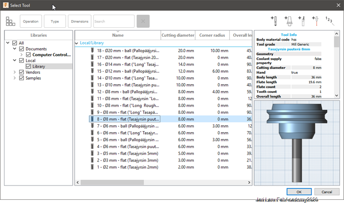
- However, because milling machine can't make a 90 degree angle, I did sketch relief into end of the slot. The radius of the milling bit is 8 mm so I did draw 8mm circles (sortcut C) at the corners of the slots
- Then I did use trim and break tools to remove uncessary construction lines and sketch lines from the design) and extruded whole sketch by using 11mmm as a thickness (material)
- This design process was done twice: once per tree
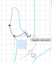
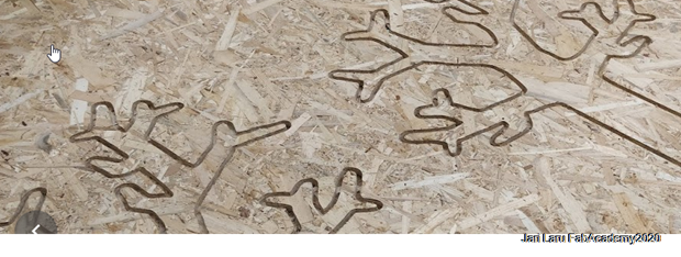
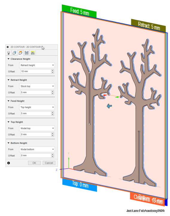
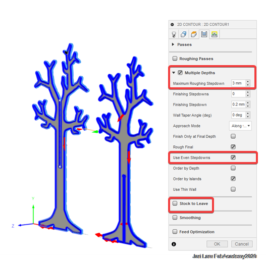
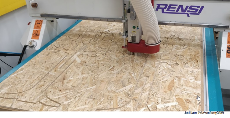
Uh-oh moment: My extruded trees can't be machined! WHAT!
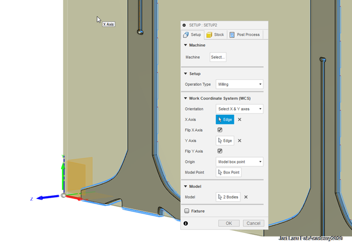
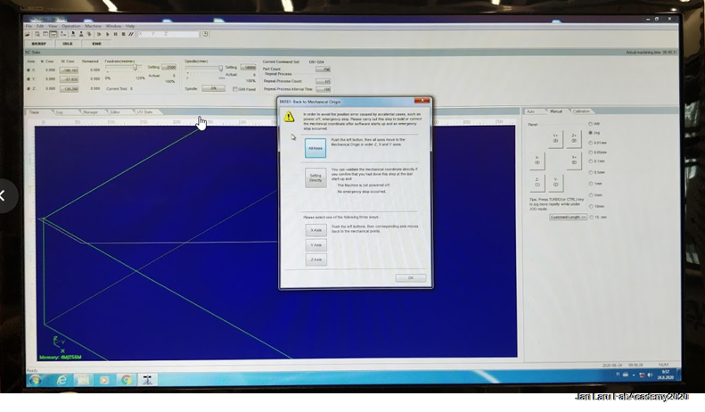
Unfortunately, approach to use SVG as a starting point wasn't appropriate way to design object for computer controlled machining. Pretty soon I noticed that I can't configure manufacture settings in the Fusion 360 without different kinds of issues and warnings.
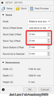
I was overwhelmed, because I thought that my design approach was pretty simple: I didn't have complicated slots, joints etc. only two pieces and two joints. So I error in generating passes was surprise. (NOTICE: manufacture settings are described just later on, this image is place here for illustrative purposes)
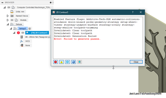
In order to continue, I did raise issue in Gitlab to get help from local instructor "eikka" with the problem. I saw him in FabLab face-to-face where he explained that my approach was "doomed", because SVGs have pretty often too detailed information and it's difficult to prepare for manufacturing in the fusion.
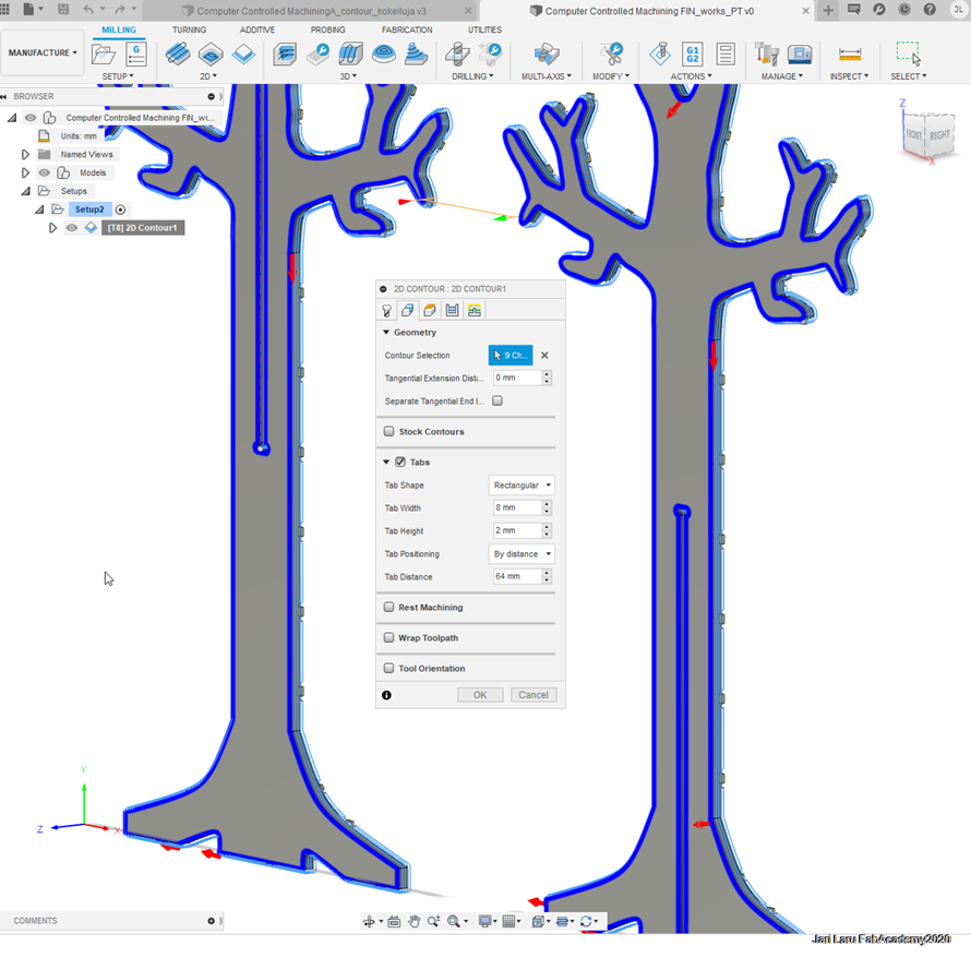
Because my design was simple, Eikka suggested that I would re-design it from the scratch. However, I decided to use my existing design as starting point - I just sketched new tree on top of the failed design by using normal sketching tools (mostly I used fit point spline tool for sketching new trees). However, I repeated phases above while creating slots, because those are so strict part of the tree instead of just copying those by sketching new sketch on top of those.

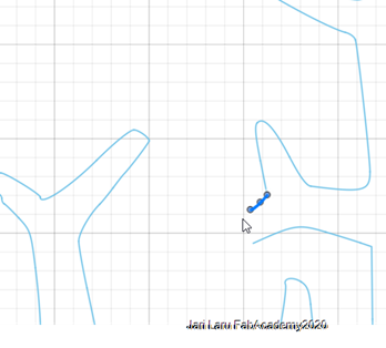
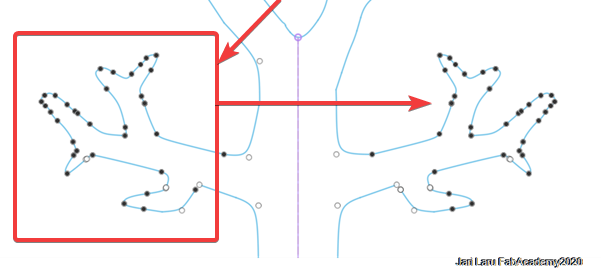
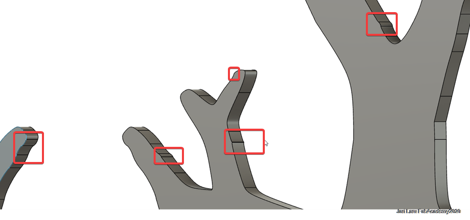
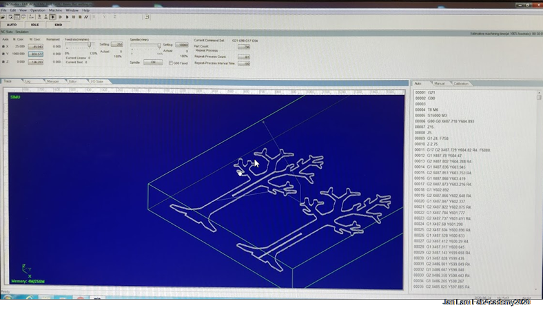
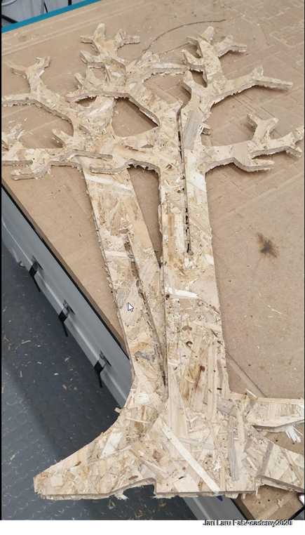
Picture below shows surface of the three, which were too much for Fusion360 manufacture settings
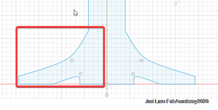
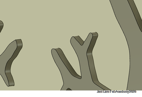
This picture (below) reveals radical change in the surface details after new design of the tree. I understand now why Fusion 360 manufacture configuration ended up into errors
Recommendations for the other designers (YOU)
If you have png/jpg image that you would like to use as basis for your design, don't use this "insert SVG" approach in the context where you are going to use 2D milling. Instead, it's suitable for 3D printing and similar purposes.
You can just import JPG or PNG directly to fusion and draw sketch on top of that. OR if you have already converted bitmap image into SVG then I recommend that you draw your sketch as a new sketch onto top of the inserted SVG.
Instead, if you have original vector graphics file (not converted from bitmap image), you can use that "insert svg" approach for 2D milling also, because then lines are "smooth"